Fixing WebGL Tile Map Seams
Published on Wednesday, December 15th, 2021
There is a common issue with tile based maps having visible seams where they shouldn't.
In this post I want to explain why they were happening to me, and to document the solutions I found that you can mix and match in your code! 😎
TLDR Show me the code and demo
The Problem
The core problem that causes seams is floating point numbers. Floating point numbers in computers do not have infinite resolution, there are "gaps" in the possible numbers that can be represented by a computer. In fact, the gaps in representable numbers get worse the further from zero you go!
This issue is super unintuitive. If you start from pure mathematics, this shouldn't be possible, but because of limited floating point precision and error accumulation seams in the geometry can happen.
Factors in the webgl that influence the issue:
- Lower pixel density screens (standard definition) seem to be easier to reproduce this problem
- The screen size and
window.devicePixelRatio(ratio between logical CSS pixels to physical screen pixels) seem to affect the appearance of these artifacts. - Large amounts (tm) of floating point manipulations of the geometry before rendering introduces and propagates floating point errors.
- Geometry manipulation
- Camera positioning
- Canvas scaling
- Texture sampling can sometimes bleed at UV's near 1.0 into adjacent pixels in your source image that you did not intend 😱 (#thanks-float-point)
Some Specifics
WebGL 1.0 is based on the OpenGL ES 2.0 spec which indicates that if the center of the fragment is not in the polygon screen pixel projection it doesn't color it in. So when the screen pixel center (0.5, 0.5) falls directly on a geometry boundary between two quads, but neither is far enough into a screen pixel for webgl to color the pixel. Mathematically this seems like it shouldn't be possible, but because of limited floating point precision there are holes in the numbers (at least with the method that Excalibur uses to build tiles).
![]()
This explanation fits with the flickering moire pattern to the left that can be seen when moving across the screen. You can see the background peaking through sometimes when the rasterizer doesn't fill in the pixel.
Solution 1 - Shared Tile Edge (best for tile maps)
If you know ahead of time that you are tiling, you can re-use the right edge of the previous tile so that there are no floating point gaps. There can be no gaps because you are using the exact same edge and not recomputing it.
Recomputing edges is where we can get into floating point trouble. Note is that this identity for the ith tile does not hold true for all floating point numbers given rounding/error, even though mathematically that is true.
i * width + width / 2 == (i + 1) * width - width / 2
Avoid recomputing edges.
So here is an example where we precompute all the x-edges and y-edges and use them to build our tile geometry
export function generateTiles(
                    tileRows: number,
                    tileColumns: number,
                    tileWidthPixels: number,
                    tileHeightPixels: number): Tile[] {

    const tiles: Tile[] = [];
    const tileXs: number[] = [];
    const tileYs: number[] = [];
    // Precompute all the x's & y's for the tile geometry
    // this keeps us from getting into trouble with floating point math
    for (let x = 0; x < (tileColumns + 1); x++) {
        tileXs[x] = x * tileWidthPixels;
    }
    for (let y = 0; y < (tileRows + 1); y++) {
        tileYs[y] = y * tileHeightPixels;
    }

    // Create tile geometry that share the same edges
    for (let x = 0; x < tileColumns; x++) {
        for (let y = 0; y < tileRows; y++) {
            const tile = new Tile({
                left: tileXs[x],
                right: tileXs[x + 1],
                top: tileYs[y],
                bottom: tileYs[y + 1]
            });
            tiles.push(tile);
        }
    }
    return tiles;
}
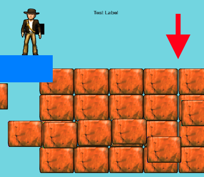
Shared Edge Solution in action
You can see the gap in far right appear and disappear
Solution 2 - Bodge the UV coordinates near 1.0
If you are resizing images on the fly to make them power-of-two dimensions or have a texture atlas with multiple sprites packed into one image, the texture sampling can bleed into the new transparent pixels. A slightly hacky work around is to back off of the UV by a small bodge factor, 0.01 but seems to work without losing actual image pixels.
 for (let i = 0; i < num; i += (size * 4)) {
        data[i + vertex + 0] = 0;
        data[i + vertex + 1] = 0;
        vertex += size;

        data[i + vertex + 0] = 0;
        data[i + vertex + 1] = (tileHeightPixels - 0.01)/ tilePOTHeight;
        vertex += size;

        data[i + vertex + 0] = (tileWidthPixels  - 0.01) / tilePOTWidth;
        data[i + vertex + 1] = 0;
        vertex += size;

        data[i + vertex + 0] = (tileWidthPixels - 0.01) / tilePOTWidth;
        data[i + vertex + 1] = (tileHeightPixels - 0.01) / tilePOTHeight;
        vertex = 0;
    }
Quick note on other texture related issues
WebGL will sample and blend pixels from other parts of a texture atlas sometimes (and is desirable for a lot of images). WebGL is trying to be helpful and picking pixels to blend next to produce high quality images.
Some additional texture consideration:
- You can change your sampling mode to
gl.NEAREST(this might not work out depending on your art style). I believe to do this in Unity this is SpriteAtlas with texture packing, and filter mode setPoint, you'll need to build/start the project. - Be sure to clamp to the edge of the texture (not useful for bleed in the atlas)
gl.texParameteri(gl.TEXTURE_2D, gl.TEXTURE_WRAP_S, gl.CLAMP_TO_EDGE);
gl.texParameteri(gl.TEXTURE_2D, gl.TEXTURE_WRAP_T, gl.CLAMP_TO_EDGE); - Add transparent padding between sprites in your texture atlas to hack around the sampler
- You can extrude the edge pixel out 1 pixel to hack around the sampler, this might be a ton of effort to update all your tiles, there are some tools that exist to do this for you.
UV Bodge In action
Notice the horizontal gap in the center of the tiles.

Solution 3 - Avoid Unnecessary Floating Point Manipulation
3.1 Unnecessary geometry scaling for HiDPI
Kronos has a good article on handling hidpi in webgl
But one important thing to keep in mind is to have your orthographic matrix mapped to your "logical" resolution (or clip space if you prefer). And keep your gl.viewport() set to the size of the hidpi scaled canvas.
If you think about it makes sense because that gl viewport is the size of the drawing surface in real machine pixels.
// logical resolution
const resolution = {
  width: 800, // "CSS" logical pixels
  height: 600 // "CSS" logical pixels
}

// hidpi scaling
function applyHiDPIScaling() {
    if (window.devicePixelRatio > 1.0) {
        canvas.width = resolution.width * window.devicePixelRatio;
        canvas.height = resolution.height * window.devicePixelRatio;

        canvas.style.width =  resolution.width + 'px';
        canvas.style.height = resolution.height + 'px';
    }
    console.log('pixel ratio', window.devicePixelRatio);
}
applyHiDPIScaling();

const shader = /*...*/
// setup orthographic 2D projection for our shaders
// Notice the orthographic is the logical resolution, not the scaled
const ortho = Matrix.ortho(0, resolution.width, resolution.height, 0, 400, -400);
shader.addUniformMatrix('u_matrix', ortho.data);

// draw frame
function draw() {
    // Clear the context with the newly set color.
    gl.clearColor(114 / 255, 213 / 255, 224 / 255, 1.0);
    gl.clear(gl.COLOR_BUFFER_BIT);

    // Use the physical scaled resolution as the viewport
    gl.viewport(0, 0, canvas.width, canvas.height);

    // Do all the drawing
    // ...
}
This eliminates the need to artificially scale your geometry (which can introduce floating point error), consider the following (which you should NOT USE)
// DO NOT USE THIS SNIPPET
applyHiDPIScaling();
const shader = /*...*/

// If we used the scaled width/height it forces use to "zoom-in" later on the geometry
const ortho = Matrix.ortho(0, canvas.width, canvas.height, 0, 400, -400);
shader.addUniformMatrix('u_matrix', ortho.data);
transform.current = Matrix.identity();

// This is applied to all geometry!! so can introduce floating point errors
transform.scale(window.devicePixelRatio, window.devicePixelRatio);
// DO NOT USE THIS SNIPPET
3.2 - Keep geometry in local coordinates for as long as possible
Do as little transformation as possible to the geometry in your pipeline. Each floating point operation is an opportunity for error to compound or propagate. If you can help it, keep geometry in local coordinates until the very last moment where you must render.
3.3 - Pixel snap
Rounding to the nearest pixel, or truncating the fraction portion can fix some issues.
However, depending on where you do your rounding or truncate the geometry might fall ahead or behind where it should in screen space. You might need to look at the "Nudge" solution to remedy this.
See this example were truncating makes it worse
3.4 - Position your camera in ideal locations
If you implement your camera by transforming the entire context, it may be a good idea to keep the camera at whole pixel values to avoid floating point issues from propagating.
Solution 0.5: "Nudge" pixels to screen (Useful for Ad-Hoc Drawing Systems)
I don't recommend this solution unless you have no other choice, or you have limited control of your drawing.
That said, this technique doesn't know if you plan to draw tiles, but if you happened to draw a tiles it will work 😎
This type of solution is covered in the beginning of OLC code zone stream #28
To fix the seam in the geometry we want to nudge the game geometry of each draw so that it will bias the left and right edge of each image to a screen pixel without a gap.
Basic algorithm:
- Map vertices to screen space
- Nudge it to the nearest screen pixel up or down
- Map vertices back to world space and use those
Our scheme to nudge pixels will be to take all our (red) right edges and add a 0.5 pixel bodge then find the ceiling, and we take all our (blue) left edges and add a 0.5 pixel bodge then find the floor.
![]()
While this works pretty well, this does have a drawback of overlapping the geometry by 1 pixel on the left or right in the majority case when the edges don't straddle the mid-pixel.
But maybe 1 pixel overlap is better than having a perceptible gap? You decide. It is a more noticeable effect if your assets are small, or your are zoomed out, because the 1 screen pixel will become a larger portion of the asset on screen.
![]()
![]()
Quick note
You might be thinking why not use ceiling for both edges (or floor) all the time to avoid overlapping by 1 pixel, well the same mid-pixel problem we were trying to solve before is now shifted to the pixel boundaries and we still have a gap.
![]()
Nudge code
It's important to multiply whatever your screen space dimensions are by the window.devicePixelRatio to account for hidpi displays. Remember that it's important to factor in the ratio between physical screen pixels and logical "css" pixels to do this mapping properly.
For HTML games
// Game resolution in "logical" pixels
// <canvas width="800" height="600" >
const resolution = {
  width: 800,
  height: 600
};

// Screen space in actual screen pixels
// <canvas style="width:800px;height:600px">
// "logical" * devicePixelRatio = physical pixels
const screen = {
  width: this.viewport.width * window.devicePixelRatio,
  height: this.viewport.height * window.devicePixelRatio
};
Map the coordinate from world "game" resolution to screen space.
function toScreenSpace(coord, resolution, screen) {
  // Map coordinate to screen space
  let screenSpacePos = vec(
    (coord.x / resolution.width) * screen.width,
    (coord.y / resolution.height) * screen.height);

  return screenSpacePos;
}
Make the inverse to map back to world space
function toWorldSpace(coord: Vector, resolution: Dimension, screen: Dimension) {
    // Map coordinate to world space
    let worldSpacePos = vec(
        (coord.x / screen.width) * resolution.width,
        (coord.y / screen.height) * resolution.height);

    return worldSpacePos;
}
Putting this all together, we apply our half pixel algorithm in both the floor and ceil
/**
 * Pushes a world space coordinate towards the nearest screen pixel (floor)
 */
export function nudgeToScreenPixelFloor(transform: Matrix, coord: Vector, resolution: Dimension): Vector {
    coord = transform.getAffineInverse().multv(coord);
    const screen = {
        width: resolution.width * window.devicePixelRatio,
        height: resolution.height * window.devicePixelRatio
    };

    let screenSpacePos = toScreenSpace(coord, resolution, screen);

    // Adjust by half a pixel "bodge" factor
    const screenSpacePosBodge = screenSpacePos.add(vec(0.5, 0.5));

    // Find the nearest screen pixel
    const nearestScreenPixelFloor = vec(
        Math.floor(screenSpacePosBodge.x),
        Math.floor(screenSpacePosBodge.y));

    // Convert back to game resolution
    const worldSpace = toWorldSpace(nearestScreenPixelFloor, resolution, screen);

    // Transform back to world coordinate
    return transform.multv(worldSpace);
}

/**
 * Pushes a world space coordinate towards the nearest screen pixel (ceiling)
 */
export function nudgeToScreenPixelCeil(transform: Matrix, coord: Vector, resolution: Dimension): Vector {
  // Same as above but with Math.ceil()
}
Putting it all together, we apply our floor nudge to the left edge, and the ceiling nudge ot the right
export function drawTile(tile: Tile) {
    // Quad update
    let topLeft = vec(tile.left, tile.top);
    let bottomRight = vec(tile.right, tile.bottom);

    topLeft = nudgeToScreenPixelFloor(transform.current, topLeft, resolution);
    bottomRight = nudgeToScreenPixelCeil(transform.current, bottomRight, resolution);

    // (0, 0) - 0
    const vertices = def.buffer.bufferData;
    vertices[vertIndex++] = topLeft.x;
    vertices[vertIndex++] = topLeft.y;

    // (0, 1) - 1
    vertices[vertIndex++] = topLeft.x;
    vertices[vertIndex++] = bottomRight.y;


    // (1, 0) - 2
    vertices[vertIndex++] = bottomRight.x;
    vertices[vertIndex++] = topLeft.y;

    // (1, 1) - 3
    vertices[vertIndex++] = bottomRight.x;
    vertices[vertIndex++] = bottomRight.y;
}
"Nudge" solution in action
Notice the semi-obvious overlap that could be undesirable in your game.
Wrapping up
There are a lot of quirks when doing tile based drawing, the majority of them boil down to floating point math or texture settings.
You may need to apply one or many solutions in this post, or remove some problematic code from your game.
Hope this helps any future explorers!
-Erik
Help support me on Github Sponsors or Patreon
Become a Patron!